Yep, all the below relates to HCs with the 4 headlight setup and is mainly from memory, dont know if it changes for the two light models?
the main live feed for the lights comes through from the fuse box at A2 under the dash (footwell side) - this is a big brown/blue wire and connects to the light switch
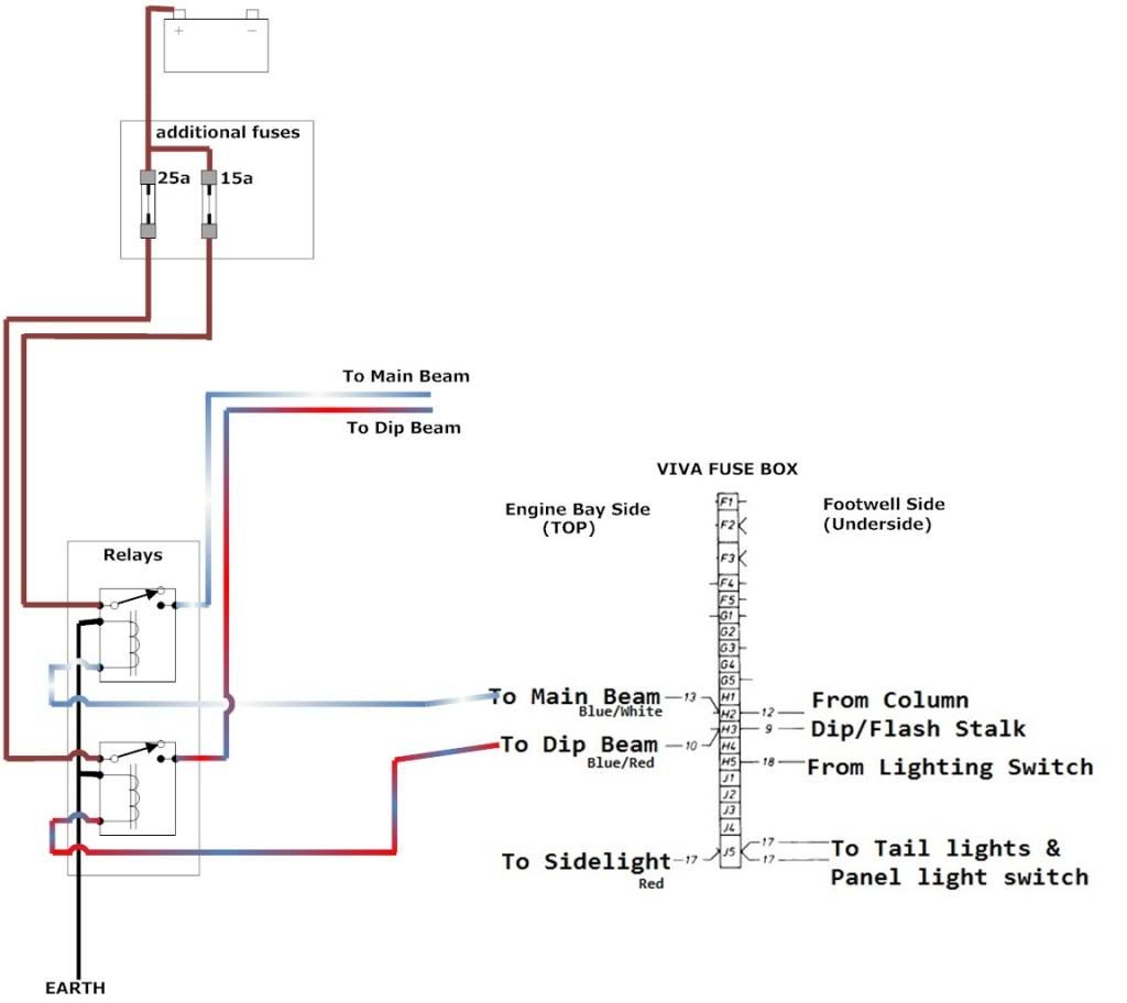
one output from the light switch is a red/green wire and goes to the fuse box at H4 under the dash (footwell side) this is connected to J5 within the fusebox via fuse 4 and feeds the sidelights, dash lights etc I chose to leave this as-is since the load is fairly small
The other output from the light switch is a blue wire and goes to the bi-metal thermal overload thingy, and from here to the flash/dip stalk - from this stalk two wires one blue/white and one blue/red go to fuse box at H2 and H3 under the dash (footwell side)
I chose to use an in-line fuse in place of the thermal cut out as all the load should be taken out of this circuit by the addition of the relays, the fuse is fairly low rated and just there incase theres a short in the switchgear prior to the relays
engine bay side i located the blue/white and blue/red wires from H2 and H3 at the fuse box (engine bay side) and disconnected them from the fuse box, connecting each to the output of a relay - i then added a new wire to H2 and H3 (engine bay side) and used them to trigger the two relays - the power feed to these relays is from the battery via a new fuse for each - the ideal rating of these will differ depending on the wattage of headlights used
a picture tells a thousand words and all that so.... heres a picture (hey its late and ive nothing better to do)
 Viewed 1288 times")
 Viewed 1288 times")


