Renault 11 oblong headlights to snoot light boxes

This is an area for discussion about modifications to Vivas.

Postby ade » Wed Dec 23, 2009 6:41 pm

Heres the allegro look pretty similiar dont they, not sure what they are on ebay

Image

And the hillman avenger ones look pretty similiar to

Image

I was told they were a fairly standard size and shape to a few seventys and eightys cars just the clips on the backs are different
Big black and loud lol
ade
GT Viva
GT Viva
 
Posts: 334
Joined: Tue Dec 27, 2005 2:47 pm
Location: TELFORD

Postby Po79 » Wed Dec 23, 2009 11:14 pm

Hi Ade,

Wasn't doubting you at all, in fact I know you know far more than I'll ever know when it comes to all things Viva.

The Allegro ones I found on Ebay look far to new to me but the ones you posted look a lot more like to me.

Po.
Po79
GT Viva
GT Viva
 
Posts: 234
Joined: Sun Jul 12, 2009 5:33 pm
Location: Burnham-on-Sea

Postby Jon-HPF » Thu Dec 24, 2009 2:39 pm

Hi Ade - Nope - dont think hey are identical - i fell for this one a few years ago - and bought a set of 4 at great expense on ebay - they are no where near the snoot cibies .
Also been mentioned that metro / dolomite / fiat 126 are similar - but thats it, they look a similar shape but when side by side with a snoot cibie the differences become very apparent .
IMO a little reworking of the appertures in the light boxes is the lesser of the two evils (rather than trying to get a set to fit perfectly in them holes) .
From a taste point of view , i preffer the strait edge look over the curved sides of the cibies - very trans am looking :D

Po - any pics of rear of the units? - They look great ! , yes slightly smaller than the r11's ive fitted - i had to cut quite a bit out of each corner to get them to sit flush , looks like u only need some minor corner cuts then just straiten the curved vertical edges back to the units .

They look like the better fit to me , cos a lot of the original cibie and indeed the r11's are hidden behind the top edge of the light box - those valeo's look like they will sit nicely on the lower edge of the box and will have nearly the lens in view (not obscured by the funny undercurve of the top of the box)
Cheers - Jon
"Thats a nice looking Capri you got there mate!"
User avatar
Jon-HPF
Brabham Viva
Brabham Viva
 
Posts: 665
Joined: Wed Oct 11, 2006 7:05 pm
Location: South wales

Postby Po79 » Tue Dec 29, 2009 10:52 am

Hi Jon,

Only just seen your post.
I'll try to get some pictures up of the rears for you soon.
Oh, i forgot to mention that the lights I have were originally made to fit the TVR Tasmin models (although some had round lights fitted).

Po.
Po79
GT Viva
GT Viva
 
Posts: 234
Joined: Sun Jul 12, 2009 5:33 pm
Location: Burnham-on-Sea

Postby Po79 » Mon Jan 04, 2010 12:30 pm

Heres the photos of the back of the Valeo lights I'll be using.

http://i369.photobucket.com/albums/oo13 ... CF4024.jpg

http://i369.photobucket.com/albums/oo13 ... CF4025.jpg

I just picked up the last one I needed from the Motor factors and they are cheaper than i was told, £30 eack.

Ok so its only a saving of £3 but over four thats £12.

Any Ideas how these could or should be mounted? Don't fancy weldind anything to them and I can't find any pictures of TVR headlights to see how these were originally fitted.

Po.
Po79
GT Viva
GT Viva
 
Posts: 234
Joined: Sun Jul 12, 2009 5:33 pm
Location: Burnham-on-Sea

Postby Jon-HPF » Mon Jan 04, 2010 7:20 pm

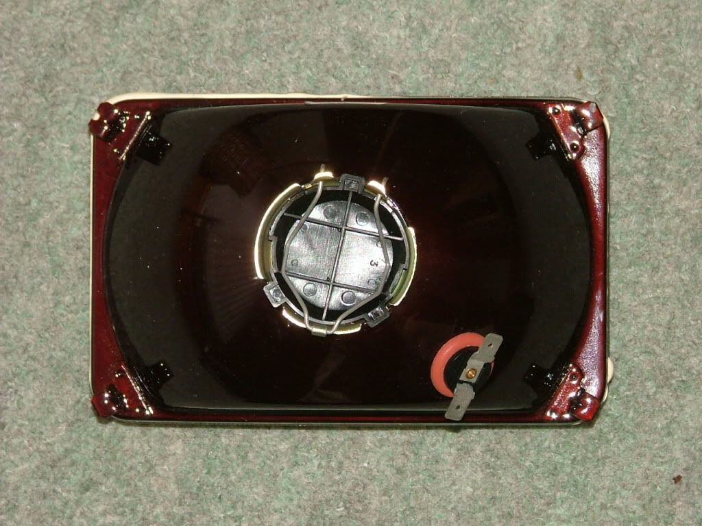
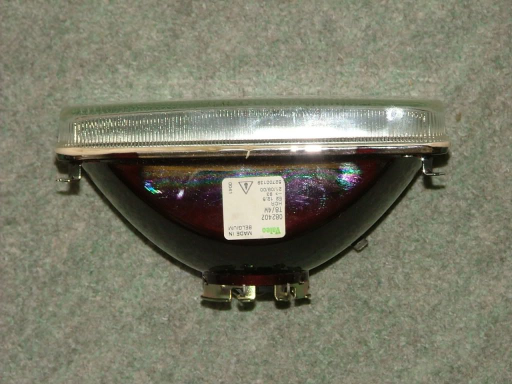
Hi Po , nice shiny new lights :lol: , did u get all 4 with side light holes ?

I understand u dont want to weld brackets to them , so you will have to make some lengthening strips and probably drill and bolt them to the little tags on each corner - i welded mine in place , but i did wrap some wet cloth around each corner to stop any heat damage to the inner silvering.
Also taped up the lens to stop any damage from the sparks :lol:

Take a look at the pics in the early part of this thread to see how i made them fit.
Basically did away with the original snoot metal plates (they were so rusty they practically fell off)
Then used 1.5mm thick stainless steel sheet and cut out the holes for each light - this was done after i had centred the lights in the boxes and reworked the holes to give a perfect fit (so the glass section just pokes into the box.)

Once each hole in the light box is correct - make a card template to get the right dimension for each backing plate (remember which light hole each one is for :oops:) Place on the back of the box , then from the front - use a thin marker pen to draw around the hole, then i used a jigsaw to cut out the centres. A tip here is to screw each backing plate onto some plyboard so that it doesnt flap around and bend the outer edges . I cut the centres a few mm's bigger so that they dont show from the front of the boxes .
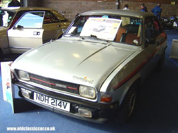
Once the backing plate is secured to the box (i used rivets) - place the light unit in the hole so that the metal part of the unit sits flat on the backing plate , hopefully , at this point the lens at the front is now all nice and square in its newly made aperture :) and no backing plate is showing.

Here's the fun bit ! - how to make adjusters , i used one stainless steel bolt for each corner bracket, around 25mm long with 8mm heads (m4 i think) , as i had welded my brackets to each corner all i had to do was line up each one and drill a corresponding hole into the backplate .
A tip here - you may wish to make your corner brackets at this point rather than doing them first - as this will give you some idea as to what angle to place them at -- I just welded each one onto the lights directly into each corner - but when i came to drill the corresponding holes in the back plates ,they were quite close to the corners and i had tp shave off some of the f/glass behind the plates to allow a captive nut to be welded in place and also to allow for adjustment of the bolts .

To stop the light unit moving on its brackets - i used some nyloc nuts and tightened them right up to the neawly made end brackets ( but not tight enough to stop the nut on the end of the bolt from turning) this ensured the lights are secure but also adjustment can be made by turning each bolt.
Then it was just a case of placing each light (along with the attached brackets and bolts/nylocs) onto each plate and hopefully all the threads line up with the holes and welded captive nuts behind the plate .

Thats how i did it -it sound long winded , but its better to learn from other peoples mistakes before you try it yourself .

I wanted to achieve a neat method without having to devise spring loadings etc so the 4 bolt idea seemed the better option .
I wish you luck - just take your time (do one light at a time and mark it to its corresponding place in each light box)
I little effort and "thinking time" will pay off in the long run

Cheers - Jon
Last edited by Jon-HPF on Mon Jan 04, 2010 9:48 pm, edited 1 time in total.
"Thats a nice looking Capri you got there mate!"
User avatar
Jon-HPF
Brabham Viva
Brabham Viva
 
Posts: 665
Joined: Wed Oct 11, 2006 7:05 pm
Location: South wales

Postby Jon-HPF » Mon Jan 04, 2010 7:38 pm

Po , from looking at your lights i dont think u will have to cut much out of each corner - heres how i did mine

Unless you intend to just use backing plates , you will have to do something similar in order to lose the vertical gaps.

Standard snoot apertures

<a href="http://s296.photobucket.com/albums/mm196/jon-hpf/?action=view&current=004.jpg" target="_blank"><img src="http://i296.photobucket.com/albums/mm196/jon-hpf/004.jpg" border="0" alt="Photobucket"></a>

cut out corners then placed units into the boxes (used masking tape on the lenses) used gaffa tape to hold lights in place while reglassed new corners in place

<a href="http://s296.photobucket.com/albums/mm196/jon-hpf/?action=view&current=015.jpg" target="_blank"><img src="http://i296.photobucket.com/albums/mm196/jon-hpf/015.jpg" border="0" alt="Photobucket"></a>

then - just a case of filling and finishing
<a href="http://s296.photobucket.com/albums/mm196/jon-hpf/?action=view&current=035.jpg" target="_blank"><img src="http://i296.photobucket.com/albums/mm196/jon-hpf/035.jpg" border="0" alt="Photobucket"></a>
<a href="http://s296.photobucket.com/albums/mm196/jon-hpf/?action=view&current=033.jpg" target="_blank"><img src="http://i296.photobucket.com/albums/mm196/jon-hpf/033.jpg" border="0" alt="Photobucket"></a>
<a href="http://s296.photobucket.com/albums/mm196/jon-hpf/?action=view&current=036.jpg" target="_blank"><img src="http://i296.photobucket.com/albums/mm196/jon-hpf/036.jpg" border="0" alt="Photobucket"></a>
<a href="http://s296.photobucket.com/albums/mm196/jon-hpf/?action=view&current=039.jpg" target="_blank"><img src="http://i296.photobucket.com/albums/mm196/jon-hpf/039.jpg" border="0" alt="Photobucket"></a>
"Thats a nice looking Capri you got there mate!"
User avatar
Jon-HPF
Brabham Viva
Brabham Viva
 
Posts: 665
Joined: Wed Oct 11, 2006 7:05 pm
Location: South wales

Postby Jon-HPF » Mon Jan 04, 2010 9:34 pm

Another idea you may wish to consider is how to fit the lightboxes without using those crappy little bolts .

The boxes themselves tend to sit in the nosecone very well so there's really no need for lots of little fidly rust trap bolts etc .
Just need a simple method to support them whilst in place :lol:

I used some stainless steel box profile , placed one piece in between the two light units - this is held in place by two bolts which were welded to the profile then fit through the backing plate of the inner light (need to drill two holes so dont need rivets in this section of plate) . the middle section of the light boxes have a good reccessed area top and bottom . this is were the nyloc nuts can be placed onto the thread and allows an "invisible" coupling to the lightbox . The box profile i used was just narrow enough to allow the inner light unit to fit !! , So it would be best u fit the lights before you make this section :oops:

The horizontal section was welded to the bottom of the vertical and a captive m8 nut welded in the other end.

<a href="http://s296.photobucket.com/albums/mm196/jon-hpf/?action=view&current=098.jpg" target="_blank"><img src="http://i296.photobucket.com/albums/mm196/jon-hpf/098.jpg" border="0" alt="Photobucket"></a>


Made a bracket which was then bolted to engine bay to allow it to be bolted together . No other bolts are used to hold the boxes in place , so i filled in the holes at the top of lightboxes and the corresponding holes in the top section of the snoot - IMO this gives a better appearance when the bonnet is open

Its best to make these brackets in situ , whilst the lightboxes are held firmly in position (gaffa tape)
<a href="http://s296.photobucket.com/albums/mm196/jon-hpf/?action=view&current=099.jpg" target="_blank"><img src="http://i296.photobucket.com/albums/mm196/jon-hpf/099.jpg" border="0" alt="Photobucket"></a>

Final step would be the lightbox glass fronts (or perspex in mine) ,
Ive covered that are in the magard snoot to real one in these forums
If you need any help or just some advice , give me a call .
Cheers - Jon
"Thats a nice looking Capri you got there mate!"
User avatar
Jon-HPF
Brabham Viva
Brabham Viva
 
Posts: 665
Joined: Wed Oct 11, 2006 7:05 pm
Location: South wales

Previous

Return to Modifications

Who is online

Users browsing this forum: No registered users and 45 guests